In some cases, after calculating an FFEA trajectory, it would be interesting to recover the atomic resolution thus leading to a multi-scale approach. Even the simplest case, where a number of FFEA conformations can be characterised at the atomic level, can be of great bio-medical relevance. As such, we have developed a procedure to map the continuum structure back to the underlying atomic structure, provided that such a structure is available.
Mapping Theory
If we build our FFEA structure from the underlying PDB structure, then at the end of the initialisation routines the continuum and atomistic structures should be aligned with one another (unless some global translation / rotation has been applied, which can be reversed). When spatially overlapped like this, the constant topology of an FFEA structure allows us to generate a linear mapping between the node of the mesh and the atoms of the PDB, which can be written as a matrix,

Where  is a non-square matrix. We can constuct this matrix by making the position of every atom,
  , a function of only the nodes forming it's containing element, or nearest element,

where  is a smaller,
  sub-matrix of . Using the shape functions of the element formed by the nodes
  , we can find the components of and use it to populate . This matrix, which is based on the equilibrium structures of both the FFEA and PDB models, can be used to convert from a non-equilibrium FFEA structure (following a simulation) to the approximately equivalent atomistic structure.
Mapping Practicality
Mapping the FFEA trajectory back onto the atomic coordinates, requires that structures in our original PDB file and our initial FFEA mesh file to be aligned correctly. In this tutorial, the FFEA mesh obtained from our EM density map have not been misaligned, but, there is no guarantee that our EM density map is aligned with our PDB file. Thus, we need to do this alignment ourselves.
Automatic Alignment
FFEAtools contains an automatic alignment tool based on the iterative closest point (ICP) algorithm. To use it, run the command
ffeatools nodepdbalign script.ffea target_pdb.pdb --node
This will rotate the nodes in the node file onto the atom positions in the PDB, minimising the RMSD between the two. For structures with an obvious alignment (e.g. a protein with one long axis), the default settings should be enough, but for structures with a more ambigous alignment (a rounder protein, for example), they won't.
By default, the algorithm picks a random set of starting positions, in order to avoid getting stuck in a local minimum. For rounder proteins, you may wish to add the –candidates flag, setting it higher than default value of 50.
For structures with multiple blobs and conformations, you can use the –bindex and –cindex flags to rotate individual blobs and conformations. By default, blob 0, conformation 0 is used.
Once the alignment has finished, make you sure to double-check that it has worked using the FFEA viewer. When loading in your FFEA file, remember to select 'Load (plainly)', as this will ensure that the pdb and the FFEA file will be loaded with the same orientation in PyMOL.
Manual Alignment
The easiest way to manually align an FFEA structure is to align the PDB to the EM map that was used to generate the mesh. It will work in this case because the mesh has not been reorientated or translated, and we will show how to do that using UCSF Chimera. However, some meshing programs translate and rotate the original frame, and in that case one would need to align the PDB with the initial mesh using our PyMOL plugin. This can be done opening PDB and mesh in PyMOL and manually aligning the former onto the later using Mouse -> 3 Button Editing.
Having said so, in order to align the PDB to the EM map, the first thing to do is to open both the PDB and EM density map in UCSF Chimera.
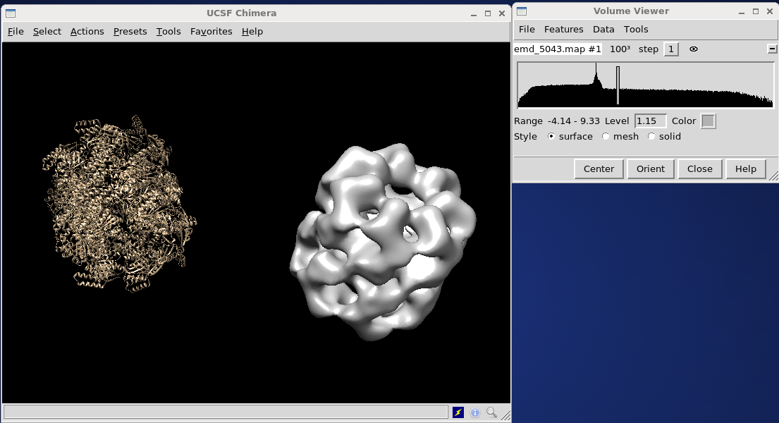
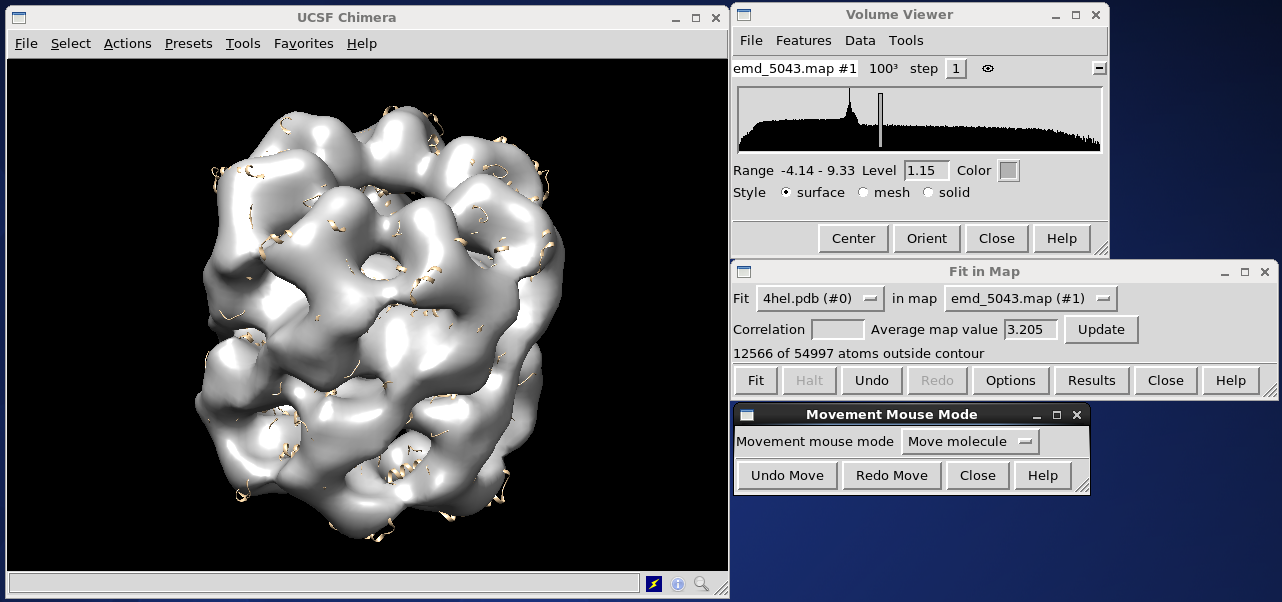
If they are not aligned, select Tools on the volume viewer menu bar, and select Volume Data, then Fit in map and push Fit. If nothing happens (as it didn't, in our example) you may need to give the algorithm some help. Without closing this window, go to the main UCSF Chimera window, under Tools, select Movement and Movement Mouse Mode. Select Move molecule from the drop-down menu, and use the middle mouse button to drag the PDB object over the electron density map. Then, use the left mouse button to rotate the PDB into the approximate correct position. Push Fit on the Fit in Map window to finish the job.
The new atomic structure can be saved by opening the file menu and selecting save PDB. For this example, we will save it as Atomicstructure.pdb.
Mapping the structure
Once an atomic structure is aligned with the FFEA mesh, the next step is to create the map between them. This is done through a number of scripts within the FFEAtools package, can be called from a front end command:
ffeatools makestructuremap -i FFEAstructure.node -t FFEAstructure.top -o Atomisticstructure.pdb -m FFEAtoatoms.map
This will use the above method to generate your mapping script. This is a highly sparse matrix, so is converted to the Yale sparse matrix format to save space before being written.
This matrix can be applied to any simulation frame calculated by FFEA in order to generate a series of atomistic structure. FFEA tools again provides a script for this procedure:
ffeatools.py maptraj FFEAtrajectory.ftj FFEAtoatomstrajectory.pdb FFEAtoatoms.map Atomisticstructure.pdb
The above script converts the entire FFEA trajectory into an atomistic one. This is done by applying the map to the FFEA trajectory (which has the same node order as the original .node file), then importing the original .pdb topology onto the new atomic positions (again, same order as the original) and writing the whole thing to a file.
Visualisation in PyMOL of both this new atomistic trajectory and the FFEA trajectory will show clearly how the mapping procedure works, but it must be emphasised that this is an entirely non-physical transformation. If atomic positions are extrapolated by the process, then bond lengths may be much greater than they should be. Interpolation of atomic positions based on the FFEA simulation can cause errors in the dihedral angles and other angular properties. If you wish to perform atomistic simulations on the back of this mapping procedure, we advise that you minimise and equilibrate the resulting atomistic structure as best you can first.